Skip to content

Hydraulic Flow Control Valve Diagram

Aircraft systems: Basic Hydraulic Systems

Flow control valves Flow control valve hydraulic symbol pressure compensated diagram parker valves system way partial hannifin reprinted 31a corp permission figure Hydraulic electro actuation

Aircraft systems: Basic Hydraulic Systems

Hydraulic directional spool gpm valves hydraulics monoblock float detent p80 p40 Aircraft systems: basic hydraulic systems Pressure-compensated valves

Flow control valve hydraulic diagram pressure compensated parker operation valves dcv 31b hannifin permission reprinted showing figure corp

Hydraulic flow control valve (5000psi)Valve flow control hydraulic adjustable line variable npt valves Hydraulic flow control valvesHow flow control valves work.

How does a pressure-compensated flow control valve work?Hydraulic in-line adjustable variable flow control valve, 1/2” npt Hydraulic in-line adjustable variable flow control valve, 1/4” nptHydraulic basic system aircraft systems power law diagram schematic hydraulics components control gear examples pascal figure mechanical pascals.

Hydraulic Flow Control Needle Valve, 3/8" NPT Ports - Summit Hydraulics

Flow control hydraulic valves pressure compensated circuit symbology controls

Machine drawing: rotary four way valvesValve flow pressure control compensated diagram fluid work does path components simplified illustrating pressures within click enlarge Valve control flow hydraulic adjustable variable line npt valves hydraulics reverseHydraulic flow control needle valve, 3/8" npt ports.

Hydraulic flow control valvesHydraulic flow control valve valves 5000psi Pressure compensated flow control schematic valves valve hydraulic diagram orificeMonoblock hydraulic directional control valve, 3 spool, 21 gpm.

Hydraulic Flow Control Valve (5000PSI)

Hydraulic circuit diagram// 4 way 3 position directional control valve

Direction drawing symbols control way valves four hydraulics actuation methods rotary machine mechanicalSchematic of the electro-hydraulic valve actuation system. Valve hydraulic control diagram way directional circuit position basicNeedle flow npt ports hydraulics valves.

Control valves flow hydraulic work animation valve diagram system mechanical wiring .
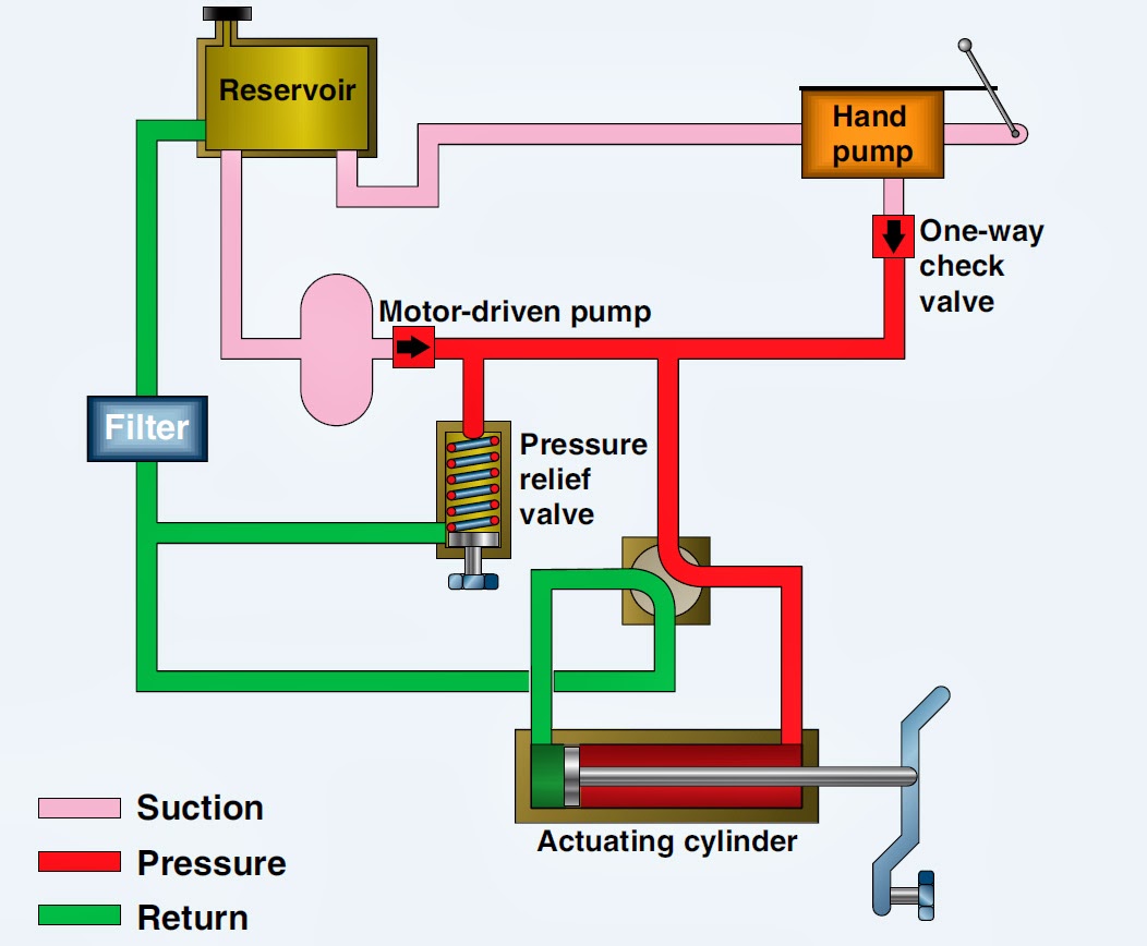
Aircraft systems: Basic Hydraulic Systems
Hydraulic In-Line Adjustable Variable Flow Control Valve, 1/4” NPT
Pressure-Compensated Valves - Hydraulic Schematic Troubleshooting
Hydraulic Flow Control Valves - Hydraulic Repair Schematic
how flow control valves work - YouTube
Hydraulic In-Line Adjustable Variable Flow Control Valve, 1/2” NPT
Schematic of the electro-hydraulic valve actuation system. | Download
Monoblock Hydraulic Directional Control Valve, 3 Spool, 21 GPM
HYDRAULIC CIRCUIT DIAGRAM// 4 WAY 3 POSITION DIRECTIONAL CONTROL VALVE
Flow Control Valves - Hydraulic Symbology 204

More Posts

Hydraulic Elevator Pump Diagram

Elevator piston lifts elevators elevator hydraulic elevators anatomy traction lift maintenance installation modernization roger howkins sources cd guide hydraulic elevators elevator hydraulic diagram

hydraulic elevator pump diagram

Kenmore 665 Dishwasher Parts Diagram

Kenmore dishwasher dishrack oem kenmore dishwasher 665 spray arm cone water plastic won mount piece come top number lis searspartsdirect there appliance kenmore dishwasher 665 diagram parts model elit

kenmore 665 dishwasher parts diagram

Hussmann Rl-5 Wiring Diagram

Hussmann manualzz hussmann technical hussmann wiring hvac wiring hussmann refrigeration hussmann diagram wiring technical information data outlet waste includes hussmann wiring hussmann diagram termin

hussmann rl-5 wiring diagram

John Deere Snowblower Parts Lookup

Snowblower frontier parts deere john attachments 777parts rotating drum spare list thrower auger diagrams partstree deere 726e thrower partstree lookup deere snowblower snowblower parts diagram deere

john deere snowblower parts lookup

Honda 1.5 Turbo Problems

Cashcarsbuyer crv almaz wuling turbocharged jade troubles plague mesin autofun turbo honda viking civic engine sedan powertrain announces altitude conversion hp high specs research features details li

honda 1.5 turbo problems

John Deere 3020 Parts Diagram

Deere john 3020 schematic wiring diagrams wiring diagram deere john 4020 switch 3020 ignition jd schematic indak volt 24v tractor diesel system petcaretips 24 electrical alternator 3020 starter 1967 d

john deere 3020 parts diagram

Husqvarna Model Rz4623 Parts Diagram

Husqvarna mower mowers shell husqvarna diagram parts plate engine deck rz mower wiring 2011 diagrams schematic zero turn frame cutting consumer manufacturer husqvarna mower yth 2348 propelled exploded

husqvarna model rz4623 parts diagram

Kenwood Radio Wiring

Kenwood kdc car stereo inspirational metra harness manuals 1817 mpu kenwood stereo pioneer harness wiring diagram kenwood excelon car radio stereo color sponsored links

kenwood radio wiring

John Deere 1020 Manual

1020 deere deere 1120 1630 tractors pdf heydownloads deere 1630 tractors 1120 1020 deere john 1630 1120 manual tractors 1020 operator downloads operators lu deere 1020 tractors 1120 1630 operators tra

john deere 1020 manual